How to Prepare Your CAD File for CNC Manufacturing (DXF, STEP, IGES)
By Adil, Managing Director at AMN Engineering · · 7 min read
You have designed your part. Now you need to send it to a manufacturer for quoting or production. But which file format should you send? What information needs to be included? And what mistakes will cause your parts to come back wrong?
This guide covers everything you need to know about preparing CAD files for CNC manufacturing, laser cutting, and metal fabrication. Follow these guidelines and your manufacturer will be able to quote accurately and produce correctly on the first attempt.
Which File Format to Send
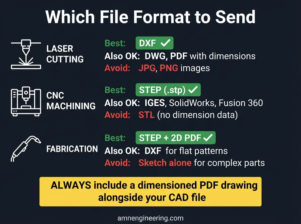
| Process | Best Format | Also Accepted | Not Ideal |
|---|---|---|---|
| Laser Cutting | DXF (2D) | DWG, PDF with dimensions | Image files (JPG, PNG) |
| CNC Machining | STEP (.stp) | IGES (.igs), SolidWorks (.sldprt), Fusion 360 (.f3d) | STL (no dimension data) |
| Metal Fabrication | STEP + 2D PDF | DXF for flat patterns, SolidWorks | Sketch alone (for complex parts) |
| All processes | Always include a 2D dimensioned PDF drawing alongside the CAD file | ||
DXF: The Standard for Flat Parts
DXF (Drawing Exchange Format) is the universal format for 2D profiles. Every laser cutter, waterjet, and plasma machine can read DXF files directly. For flat sheet metal parts (brackets, panels, guards, enclosures), DXF is all you need.
STEP: The Standard for 3D Parts
STEP (.stp or .step) is the universal format for 3D solid models. Every CAD and CAM system can import STEP files. For CNC machined parts with complex 3D geometry, STEP is the best format because it preserves all geometric data without software specific formatting.
IGES: The Older Alternative to STEP
IGES (.igs) is an older 3D format. It works but can sometimes have surface stitching issues (gaps between surfaces). If possible, use STEP instead. If your software only exports IGES, it is still usable.
PDF: Always Include One
A dimensioned PDF drawing should accompany every CAD file. The PDF serves as the human readable reference that shows dimensions, tolerances, material specifications, surface finish, thread callouts, and notes. The CAD file gives the machine geometry. The PDF gives the manufacturer context.
What to Include in Your File
In Your CAD File (DXF or STEP):
- Correct geometry at 1:1 scale (actual size, not scaled)
- Closed profiles (no open lines or gaps in DXF contours)
- Single layer for the cutting profile (DXF)
- No duplicate lines sitting on top of each other
- No construction lines, notes, or dimensions in the DXF cutting file
In Your 2D PDF Drawing:
- All critical dimensions with tolerances
- Material specification (e.g., EN8, SS304)
- Surface finish requirements (e.g., Ra 3.2)
- Thread specifications (BSP, metric, UNC with size and pitch)
- Coating requirements (galvanizing, powder coating, plating)
- General tolerance note
- Any special notes (heat treatment, testing, certification)
7 Common Mistakes That Cause Problems
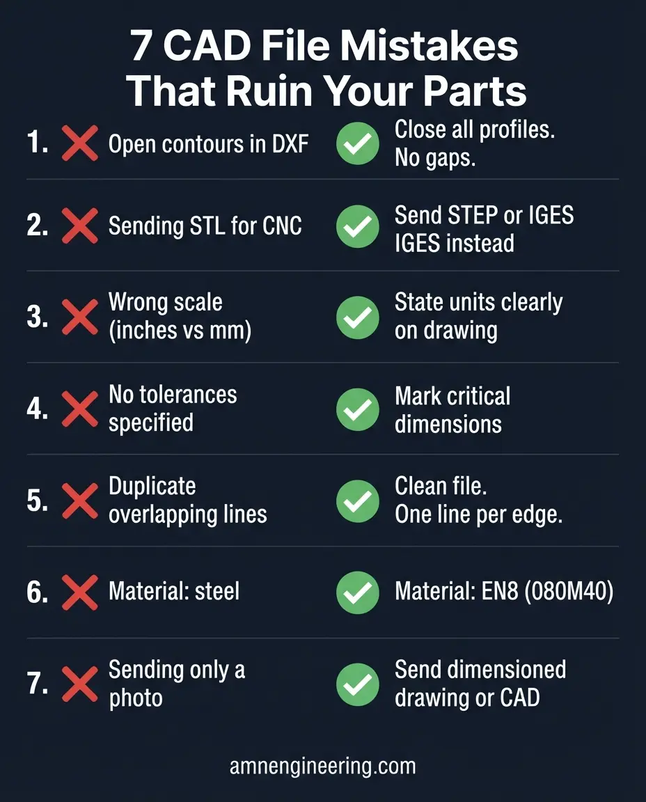
Mistake 1: Open Contours in DXF Files
If the lines in your DXF do not form a completely closed shape, the laser cutter cannot determine what is inside and outside. Always verify that all profiles are closed (start and end points connected).
Mistake 2: Sending an STL File for CNC Machining
STL files are triangulated mesh models used for 3D printing. They do not contain actual dimension data, curves, or surface information. A cylinder in STL is actually a collection of flat triangles approximating a circle. CNC machines need true geometric data (STEP or IGES).
Mistake 3: Wrong Scale
If your part is designed in inches but the manufacturer reads it as millimeters, everything will be 25.4 times too small. Always verify the unit system. State "All dimensions in mm" or "All dimensions in inches" on the drawing.
Mistake 4: Missing Tolerances
If you do not specify tolerances, the manufacturer assumes general workshop tolerance (plus or minus 0.1 to 0.5mm depending on the process). If you need tighter than that on certain dimensions, mark them explicitly.
Mistake 5: Duplicate Lines
DXF files sometimes have two identical lines sitting on top of each other. This causes the laser to cut the same path twice, resulting in overcut edges and wider kerf. Clean your DXF file before sending.
Mistake 6: No Material Specification
"Steel" is not a material specification. There are hundreds of steel grades at different prices and properties. Specify the exact grade or describe the application so the manufacturer can recommend one.
Mistake 7: Sending Only a Photo
A photo of an existing part cannot be manufactured from. It has no dimensions, no tolerances, no material specification. If you only have a physical sample, measure it and create a drawing, or send the sample to the manufacturer for reverse engineering.
Checklist Before Sending Your File
Use this checklist before sending your file to any manufacturer:
- CAD file is in the correct format (DXF for flat, STEP for 3D)
- File is at 1:1 scale in the correct unit (mm or inches, stated clearly)
- All contours are closed (DXF: no gaps in profiles)
- No duplicate lines or overlapping geometry
- No construction lines in the cutting file (DXF)
- A dimensioned PDF drawing is included alongside the CAD file
- Material is specified with exact grade
- Tolerances are marked on critical dimensions
- Surface finish is specified where required
- Thread specifications include standard, size, and pitch
- Coating or treatment is specified
- Quantity and delivery details are included
- Any special notes (heat treatment, testing, certifications) are stated
Frequently Asked Questions
DXF is the standard for laser cutting. It contains the 2D profile that the laser follows directly. Always include a dimensioned PDF alongside it.
STEP (.stp) is the best format for CNC machined parts. It preserves all 3D geometry. Include a 2D dimensioned PDF with tolerances and notes.
Yes. Most manufacturers can open native CAD files. However, STEP is safer because it is universal and avoids version compatibility issues.
For simple parts, yes. A dimensioned sketch with material and tolerances is enough for an initial quote. For complex parts, a proper CAD file gives more accurate results.