CNC Turning vs CNC Milling: Which Process Fits Your Part?
By Adil, Managing Director at AMN Engineering · · 12 min read
CNC turning vs CNC milling. Two of the most common machining processes in manufacturing, and engineers regularly specify the wrong one. Getting this decision right can save you 20 to 40 percent on machining costs, reduce lead time, and improve the quality of your finished parts.
This guide explains the difference between CNC turning and CNC milling in plain language. No textbook definitions. Just a practical comparison to help you choose the right process for your part, based on 25 years of running both processes at our factory in Lahore.
The Simple Rule
Here is the easiest way to decide:
Is your part round or cylindrical? Use CNC turning.
Does your part have flat surfaces, pockets, or complex shapes? Use CNC milling.
Does it have both round features AND flat features? You need both processes, or a turn mill machine that does both in one setup.
That single question ("is it round?") gets you the right answer about 80 percent of the time. Now let us look at why.
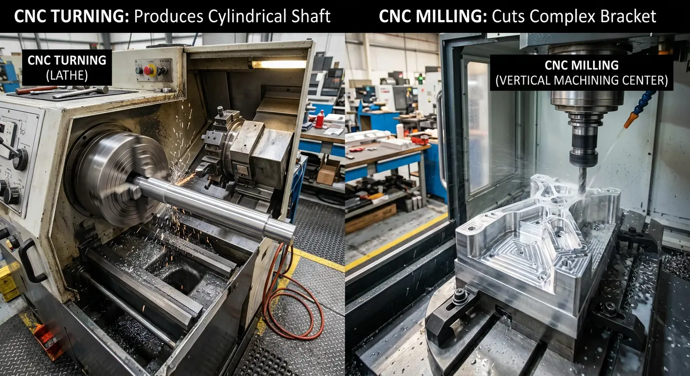
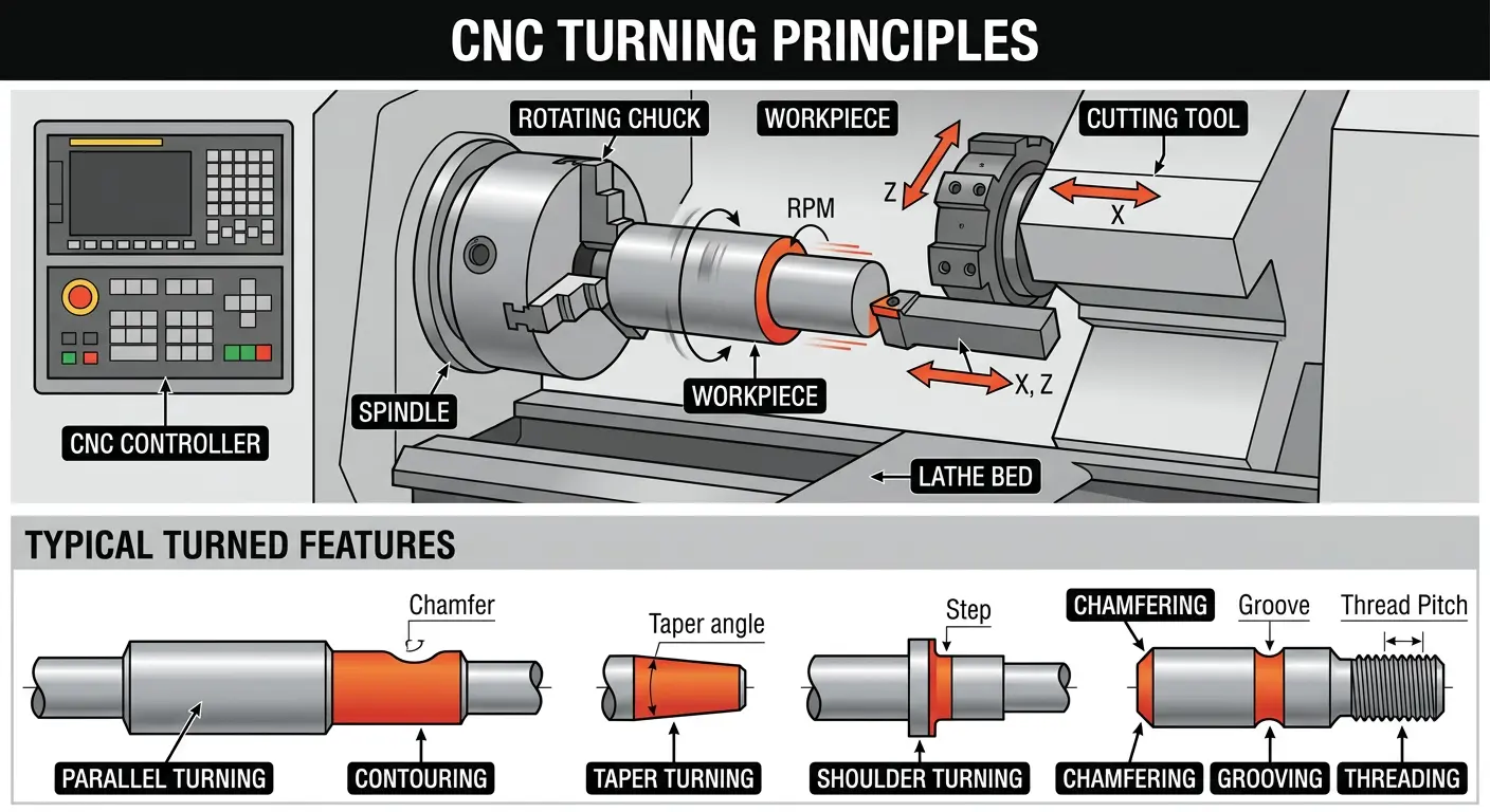
How CNC Turning Works
In CNC turning, the workpiece (your raw material) is clamped in a rotating chuck. The chuck spins the material at high speed, typically 500 to 3,000 RPM depending on the material and diameter. A stationary cutting tool then moves along the spinning workpiece, removing material to create the desired shape.
Think of it like a pottery wheel. The material spins, and the tool shapes it.
What Turning Can Do
Because the workpiece rotates, turning naturally produces round shapes. The process can create:
- External diameters (the outside of a shaft or tube)
- Internal bores (holes through the center)
- Tapers (gradually changing diameter)
- Threads (internal and external)
- Grooves and undercuts
- Chamfers and radii on edges
- Knurled surfaces (diamond pattern grip textures)
What Turning Cannot Do
Turning cannot easily create flat surfaces, pockets, slots, or features that are not centered on the axis of rotation. If your part needs a keyway, a mounting hole pattern, or a milled flat, you will need a secondary milling operation (or a turn mill machine).
How CNC Milling Works
In CNC milling, the workpiece is clamped stationary on a table. A rotating cutting tool (the milling cutter) moves across the workpiece in multiple directions (X, Y, and Z axes) to remove material. On a 3 axis mill, the tool moves in three directions. On a 5 axis mill, the tool can also tilt and rotate, allowing it to reach complex angles and undercuts.
Think of it like a drill that can also move sideways. The tool spins and carves shapes out of the material.
What Milling Can Do
Milling is extremely versatile. It can create:
- Flat surfaces and faces
- Pockets (recessed areas)
- Slots and channels
- Holes (drilled, bored, or reamed)
- Complex 3D contours and profiles
- Threads (with thread mills)
- Chamfers and radii
- Features on multiple faces of the part
What Milling Does Less Efficiently
Milling can technically produce round shapes, but it does so much slower than turning. Machining a simple shaft on a mill would take 3 to 5 times longer than turning the same shaft on a lathe. That extra time means higher cost.

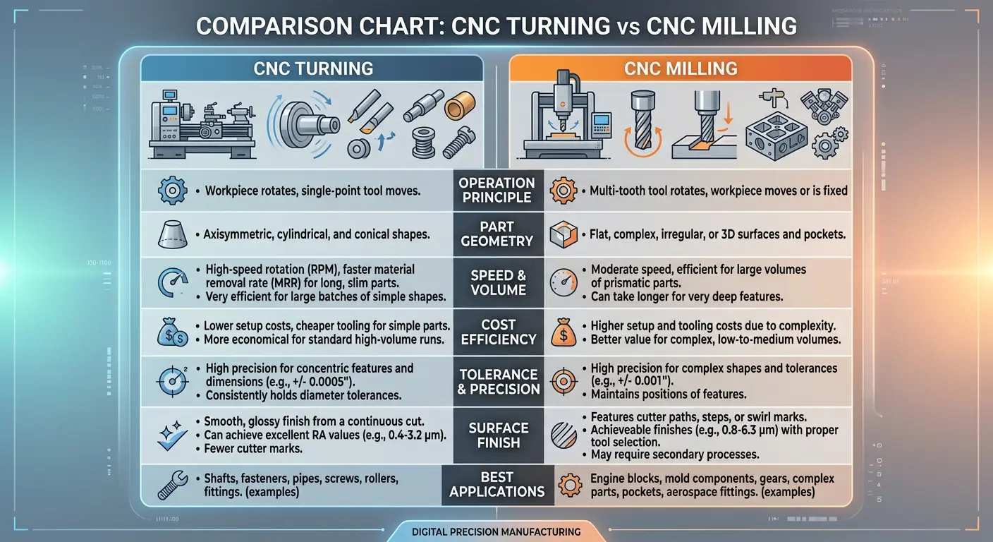
The Full Comparison Table
| Factor | CNC Turning | CNC Milling |
|---|---|---|
| How It Works | Workpiece rotates, tool is stationary | Tool rotates, workpiece is stationary |
| Best For | Round and cylindrical parts | Flat, complex, and multi face parts |
| Typical Parts | Shafts, bushings, pins, rollers, pulleys | Brackets, housings, plates, valve bodies |
| Axes | 2 axis standard, 4 axis with live tooling | 3 axis standard, 5 axis for complex work |
| Speed | Very fast for round parts | Moderate, depends on complexity |
| Cost for Round Parts | Lower (20 to 40% cheaper) | Higher (slower process) |
| Cost for Complex Parts | Not possible for most complex shapes | Standard process |
| Tolerance | Plus or minus 0.01mm achievable | Plus or minus 0.01mm achievable |
| Surface Finish | Excellent (Ra 0.8 to 3.2 typical) | Good (Ra 1.6 to 6.3 typical) |
| Material Waste | Lower (efficient material removal) | Higher (more tool paths needed) |
| Setup Time | Shorter (simpler fixturing) | Longer (complex fixturing for multi face work) |
| Max Part Size | Limited by chuck diameter and bed length | Limited by table size |
Cost: Which Process Is Cheaper?
For Round Parts: Turning Saves 20 to 40 Percent
If your part is cylindrical, turning is almost always cheaper than milling. The reasons are straightforward:
Faster material removal. A lathe removes material very efficiently on round parts because the entire circumference is being cut simultaneously as the workpiece rotates. A mill would have to trace around the outside of the same shape, which takes much longer.
Simpler fixturing. Chucking a round bar in a lathe takes seconds. Setting up a milling fixture for the same part takes minutes. Over a batch of 500 parts, this difference adds up.
Fewer tool changes. A typical turned part might use 3 to 5 tools. A milled equivalent might need 6 to 10 tools with more complex tool paths.
Real example from our factory: A pump shaft in EN8 steel, 200mm long, 40mm diameter, with two bearing seats and a thread. On the lathe, this part takes about 8 minutes. If we tried to produce the same shape on a milling machine, it would take roughly 25 minutes. The turning cost is about 35 percent lower.
For Complex Parts: Milling Is the Only Option
If your part has flat surfaces, pockets, holes on multiple faces, or irregular geometry, milling is the only practical process. Comparing cost with turning does not apply because turning simply cannot produce these shapes.
When Both Processes Are Needed
Many parts need both turning and milling. In this case, the total cost depends on the sequence and whether you can combine operations on a single machine. Parts that require both processes typically cost 30 to 50 percent more than parts that need only one process.
Tolerances and Surface Finish
Turning Tolerances
| Tolerance Level | Range | Application |
|---|---|---|
| Standard | Plus or minus 0.05mm | General engineering parts |
| Precision | Plus or minus 0.02mm | Bearing seats, seal surfaces |
| High precision | Plus or minus 0.01mm | Instrument parts, gauges |
Turning produces excellent surface finishes. A standard turned surface is typically Ra 1.6 to 3.2 micrometers. With fine finishing passes, Ra 0.8 is achievable. For even finer finishes, grinding after turning can reach Ra 0.2 to 0.4.
Milling Tolerances
| Tolerance Level | Range | Application |
|---|---|---|
| Standard | Plus or minus 0.05 to 0.1mm | General brackets, plates |
| Precision | Plus or minus 0.02 to 0.05mm | Housings, valve bodies |
| High precision | Plus or minus 0.01mm | Mold components, aerospace |
Milling surface finish is typically Ra 1.6 to 6.3 depending on the cutter, speed, and material. Fine milling with small stepovers can achieve Ra 0.8, but this is slower and more expensive than achieving the same finish by turning.
When Your Part Needs Both Processes
Many real world parts require both turning and milling. Common examples:
Shafts with keyways. The shaft body is turned on a lathe. The keyway slot is then milled. Two setups, two machines.
Flanges with bolt holes. The flange body is turned (round shape, bore, face). The bolt hole pattern is then drilled and milled.
Valve bodies. The main bore and sealing surfaces are turned. The ports, mounting faces, and pockets are milled.
Turn Mill Machines: Both in One Setup
Modern CNC turn mill machines (also called mill turn centers) combine lathe and milling capabilities in a single machine. The workpiece sits in the lathe chuck, but the machine also has a milling spindle that can cut flats, pockets, and holes while the part is still chucked.
The advantage is significant: no re fixturing between machines. This eliminates the alignment errors that happen when you move a part from a lathe to a mill. It also reduces lead time because you skip an entire setup step.
At AMN Engineering, we use turn mill capability for parts that need both processes. This gives our clients better accuracy and faster delivery compared to shops that run parts across two separate machines.
Common Parts Made by CNC Turning
If your part looks like any of these, turning is the right process:
Shafts and spindles. Pump shafts, motor shafts, drive shafts, spindles. Any long cylindrical part with varying diameters, shoulders, and bearing seats.
Bushings and sleeves. Cylindrical parts with a bore through the center. Used as wear surfaces, spacers, or guide elements.
Pins and rollers. Solid cylindrical parts used in assemblies, conveyor systems, or mechanical linkages.
Threaded rods and fasteners. Parts with external or internal threads. Threading on a CNC lathe is fast and accurate.
Pulleys and couplings. Round parts with grooves, keyways, or set screw holes (the grooves are turned, the keyways are milled in a secondary operation).
Flanges. Round plates with a center bore, bolt circle, and sealing faces.
Common Parts Made by CNC Milling
If your part looks like any of these, milling is the right process:
Brackets and mounting plates. Flat parts with holes, slots, and bent flanges. Often made from laser cut blanks and then milled to final dimensions.
Housings and enclosures. Box shaped parts with internal pockets, mounting features on multiple faces, and precise bore locations.
Valve bodies and manifolds. Complex parts with intersecting bores, ports, and sealing surfaces on multiple faces.
Mold components. Cores, cavities, and inserts for die casting molds. These require 3 axis or 5 axis milling for complex 3D surfaces.
Custom fixtures and tooling. One off parts used to hold, locate, or inspect other parts during manufacturing.
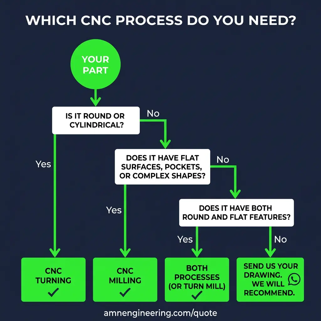
How to Decide: A Quick Flowchart
Ask yourself these questions in order:
Question 1: Is your part round or cylindrical?
Yes: CNC Turning. No: Go to Question 2.
Question 2: Does your part have flat surfaces, pockets, or features on multiple faces?
Yes: CNC Milling. No: Go to Question 3.
Question 3: Does your part have BOTH round features AND flat/complex features?
Yes: Both processes needed (or a turn mill machine). No: Send us your drawing and we will recommend the best process.
Still not sure? That is completely normal. Send us your drawing on WhatsApp and we will tell you exactly which process (or combination) will give you the best result at the lowest cost. We do this every day.
Frequently Asked Questions
In CNC turning, the workpiece rotates while a stationary cutting tool removes material. In CNC milling, the workpiece stays still while the cutting tool rotates and moves across the material. Turning is best for round or cylindrical parts like shafts and bushings. Milling is best for flat surfaces, pockets, slots, and complex geometries.
For cylindrical parts, CNC turning is usually 20 to 40 percent cheaper than milling because the process is faster and simpler. Turning removes material quickly on round parts, uses fewer tool changes, and requires less complex programming. However, for flat or complex shaped parts, milling is the only practical option regardless of cost.
Yes. Many parts require both processes. For example, a shaft that is round (turned) but also has a keyway slot or flat (milled). Modern CNC turn mill machines can do both operations in a single setup, which reduces cost and improves accuracy by eliminating re fixturing between machines.
Both CNC turning and CNC milling can achieve tolerances of plus or minus 0.01mm on precision work. Standard tolerances for general engineering are plus or minus 0.05mm for turning and plus or minus 0.05 to 0.1mm for milling. Achieving tighter tolerances increases cost due to slower cutting speeds and additional inspection requirements.
CNC turning is best for any part that is round or cylindrical in shape. Common examples include shafts, pins, bushings, rollers, spacers, threaded rods, pulleys, couplings, and bearing housings. If you can describe your part as round, tubular, or having a circular cross section, turning is almost certainly the right process.
CNC milling is best for parts with flat surfaces, pockets, slots, holes in multiple directions, and complex 3D shapes. Common examples include brackets, housings, valve bodies, manifolds, mounting plates, enclosures, and any part with features on multiple faces. If your part has flat surfaces or non round geometry, milling is the right process.