What Is GD&T and Why It Matters for Manufactured Parts
By Adil, Managing Director at AMN Engineering · · 9 min read
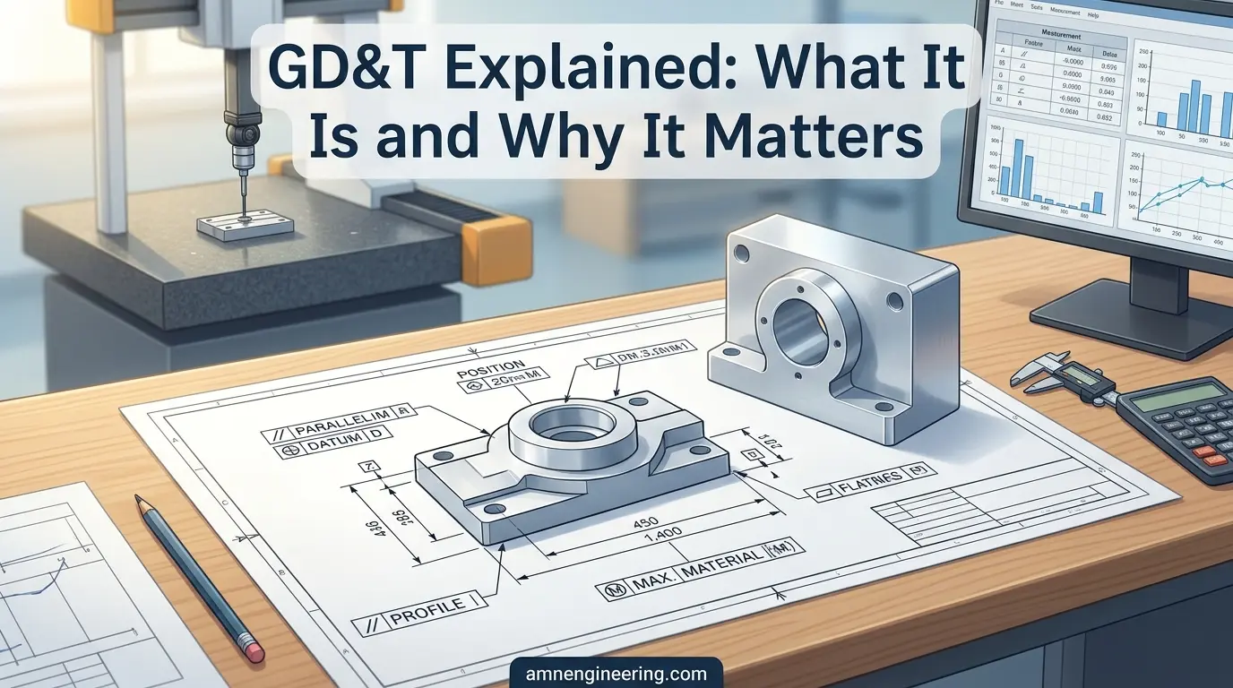
If you have ever received an engineering drawing covered in symbols inside rectangular boxes, you have seen GD&T. It is the standardized language that tells a manufacturer exactly how much variation is allowed in the shape, size, orientation, and location of every feature on a part. Get it right and your parts fit together and function; get it wrong and you pay for rejects and rework.
This guide explains what GD&T means in plain language, how the 14 symbols work, how datum references anchor every measurement, and when you actually need GD&T versus simple plus or minus tolerancing on your drawings.
We read and interpret GD&T drawings every day at AMN Engineering. What follows comes from 25+ years of machining precision parts in Lahore and verifying geometric tolerances for clients across the GCC, Europe, and the USA.
What Is GD&T?
GD&T stands for Geometric Dimensioning and Tolerancing. It is a standardized language of symbols, rules, and definitions used on engineering drawings. GD&T tells a manufacturing team exactly how much variation is allowed in the shape, size, orientation, and location of every feature on a part.
The system is governed by the ASME Y14.5 standard in North America and the ISO 1101 standard internationally. Both serve the same purpose: they give engineers, machinists, and quality inspectors a universal way to communicate exactly what a part needs to look like.
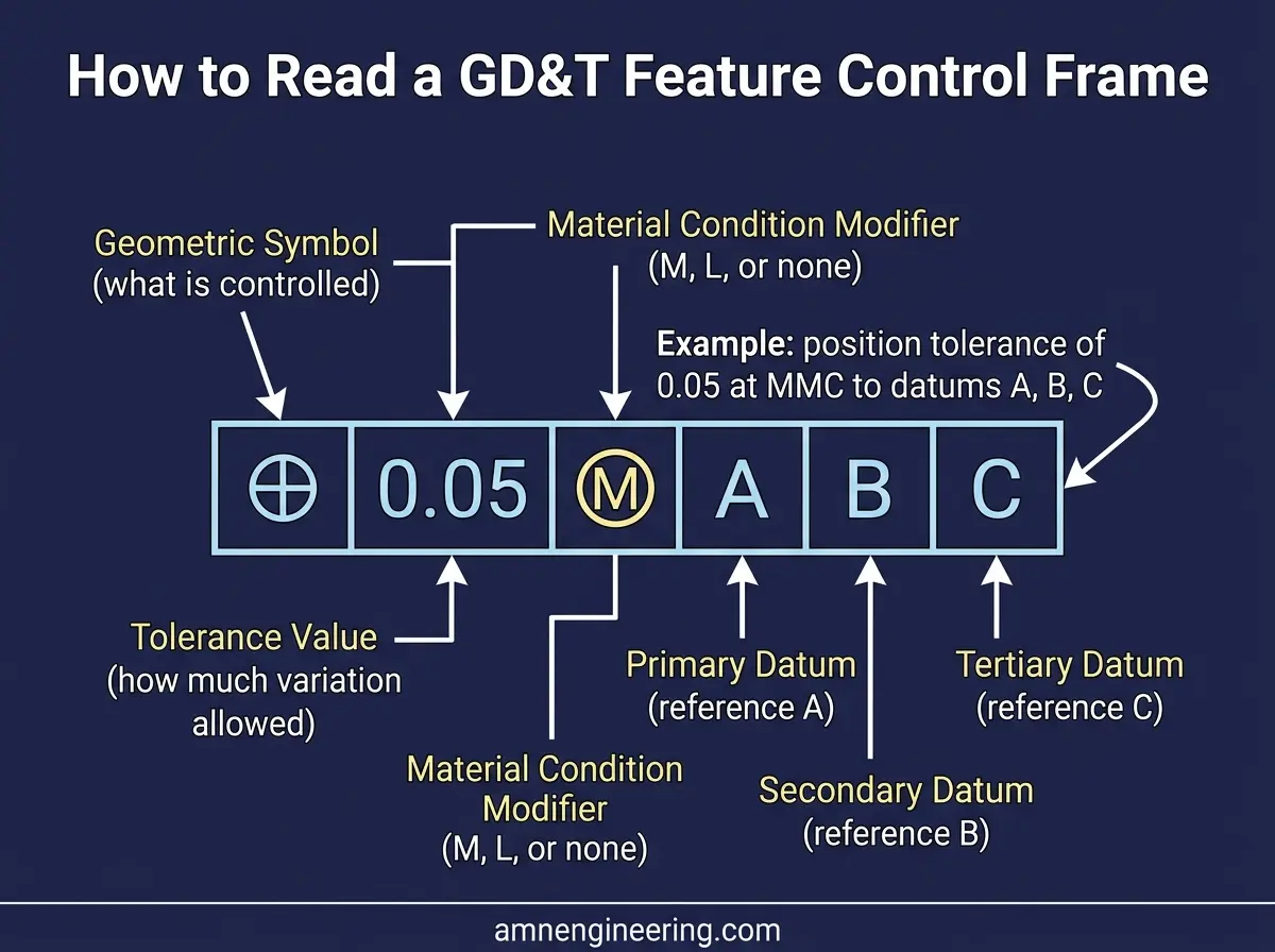
If you have ever received a drawing with symbols inside rectangular boxes connected by leader lines, those are GD&T callouts. Each symbol tells the manufacturer something specific about how a feature must be shaped, oriented, or positioned. That boxed callout is called a feature control frame, and it is where the symbol, the tolerance value, and the datum references all come together.
Why GD&T Matters in Manufacturing
For buyers sourcing custom CNC machined parts or precision ground components, GD&T matters for several reasons.
It Controls Geometry, Not Just Size
Basic tolerancing using plus or minus values only controls the size of a feature. GD&T goes further by controlling the shape, orientation, and position of that feature. For example, a hole might be the correct diameter but drilled at a slight angle. Basic tolerancing would not catch this, but a GD&T perpendicularity callout would.
It Reduces Rejected Parts
GD&T uses circular and cylindrical tolerance zones instead of the square zones created by plus or minus tolerancing. A circular zone gives you about 57 percent more usable area than a square zone of the same width. This means more parts pass inspection without sacrificing function. Our machining tolerance visual guide shows how those tolerance zones look in practice.
It Eliminates Confusion
Without GD&T, two different machinists might interpret the same drawing differently. GD&T removes this ambiguity by defining exactly where measurements are taken from (datums) and exactly how much variation is allowed in each direction.
It Ensures Parts Fit Together
When multiple parts must assemble together, GD&T ensures that every feature on every part is positioned accurately enough for the assembly to work. This is especially important for parts with multiple holes, mating surfaces, or alignment features.
The 14 GD&T Symbols Simplified
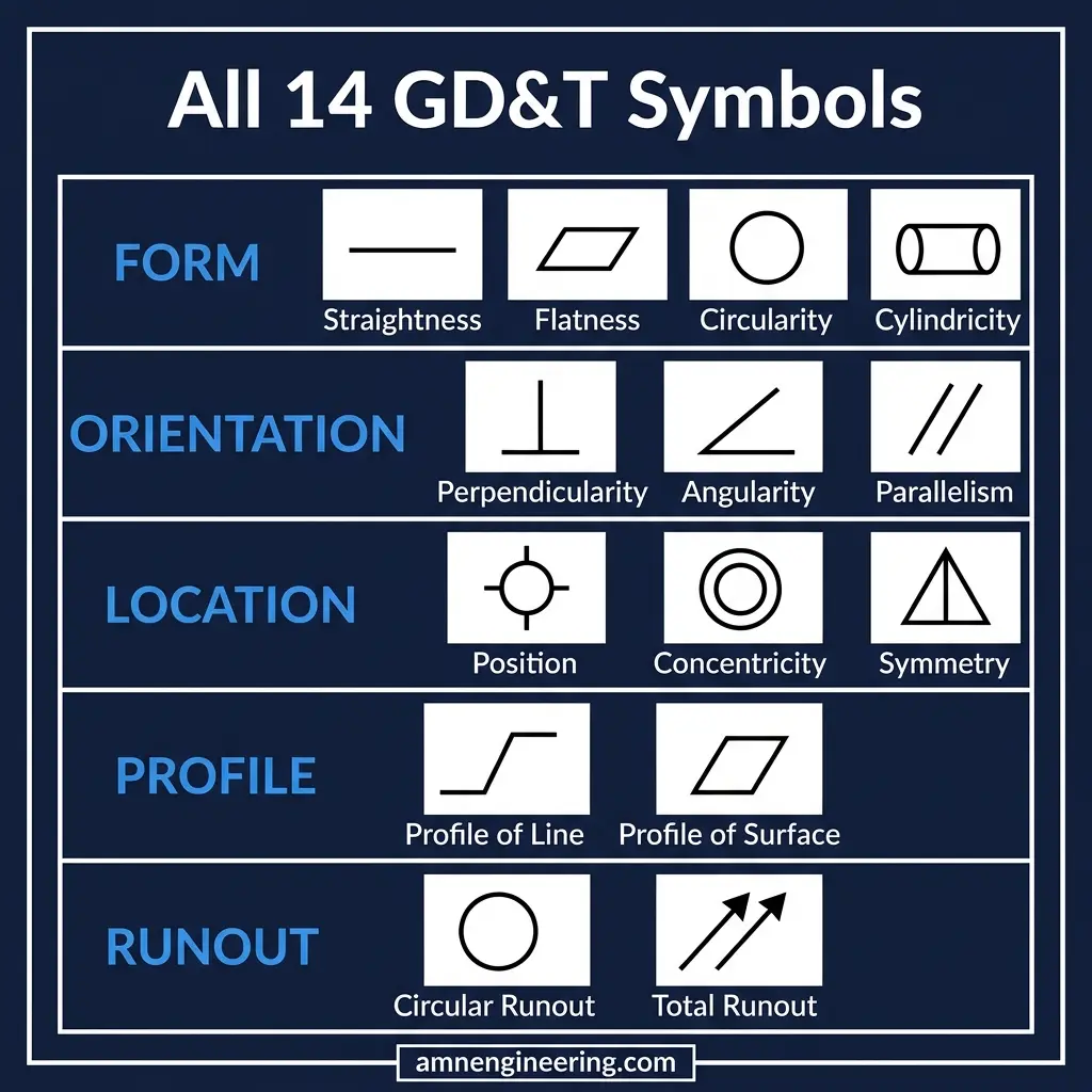
The ASME Y14.5 standard defines 14 geometric tolerance symbols, organized into five categories. Here is a simplified overview of each one.
Form Controls (Shape of a Single Feature)
| Name | What It Controls |
|---|---|
| Flatness | How flat a surface must be |
| Circularity (Roundness) | How round a cross section must be |
| Cylindricity | How perfectly cylindrical a surface must be |
| Straightness | How straight a line or axis must be |
Form controls do not need a datum reference. They control the shape of a single feature on its own.
Profile Controls
| Name | What It Controls |
|---|---|
| Profile of a Line | Shape of a 2D cross section |
| Profile of a Surface | Shape of a complete 3D surface |
Profile controls can work with or without datum references. They are useful for complex curved surfaces.
Orientation Controls
| Name | What It Controls |
|---|---|
| Perpendicularity | How square a feature is to a datum |
| Angularity | How accurate an angle is to a datum |
| Parallelism | How parallel a feature is to a datum |
Orientation controls always require at least one datum reference.
Location Controls
| Name | What It Controls |
|---|---|
| True Position | Exact location of a feature center |
| Concentricity | How well two features share a center axis |
| Symmetry | How evenly a feature is distributed about a center |
Location controls are the most commonly used GD&T callouts, especially true position for hole patterns.
Runout Controls
| Name | What It Controls |
|---|---|
| Circular Runout | Variation at any single cross section when rotated |
| Total Runout | Variation across the entire surface when rotated |
Runout controls are essential for rotating parts like shafts, spindles, and hubs.
Understanding Datum References
A datum is a reference feature on your part that serves as the starting point for all measurements. Think of it as the anchor point that everything else is measured from.
How Datums Work
Datums are labeled with letters (A, B, C) on the drawing. The primary datum (A) is usually the largest flat surface or the most important functional surface. The secondary datum (B) establishes orientation, and the tertiary datum (C) locks the part into a specific position.
Why Datums Matter
Without datums, two inspectors measuring the same part could get different results because they are measuring from different points. Datums make sure everyone measures from the same reference, whether you are in a factory in Pakistan, an inspection lab in Germany, or a receiving dock in Dubai. If you are new to reading these callouts, start with our guide on how to read an engineering drawing.
Datum Selection Tips for Buyers
When creating your drawing, choose datums that match how the part will be mounted or used in its assembly. For example, if a bracket mounts on a flat surface with two bolts, the flat mounting surface should be Datum A and the bolt holes should be Datum B and C.
GD&T vs Basic Tolerancing
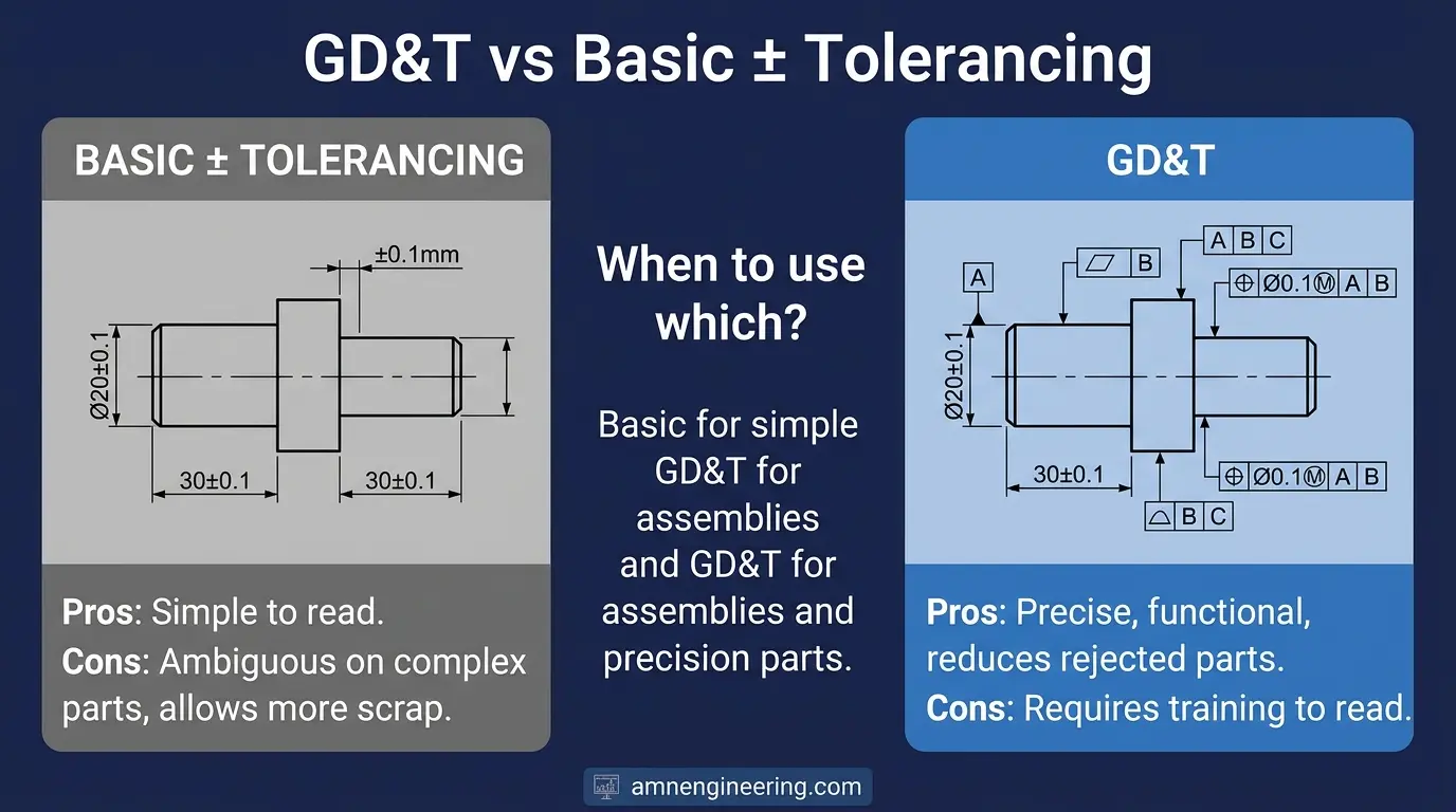
Here is a comparison of when basic tolerancing works and when GD&T is the better choice.
| Factor | Basic Tolerancing (± Values) | GD&T |
|---|---|---|
| Controls size | Yes | Yes |
| Controls shape | No | Yes |
| Controls position | Limited | Yes, with true position |
| Tolerance zone shape | Square/rectangular | Circular/cylindrical |
| Usable tolerance area | Baseline | 57% more than basic |
| Requires datums | No | Yes, for most controls |
| Complexity | Simple | Moderate to complex |
| Best for | Simple parts, single features | Assemblies, mating parts, precision work |
When Basic Tolerancing Is Enough
For simple parts with few features, basic tolerancing works well. A flat plate with a few holes on generous tolerances does not need GD&T. A simple turned shaft with a diameter tolerance and a length tolerance is straightforward with plus or minus values.
When You Need GD&T
GD&T becomes necessary when your part has multiple features that must work together. Bolt hole patterns, bearing bores, mating flanges, and alignment pins all benefit from GD&T because it controls how features relate to each other, not just how big they are.
Real World Examples of GD&T in Action
Example 1: Pump Housing with Bearing Bores
A pump housing has two bearing bores that must be concentric (share the same center axis). If the bores are off center by even 0.05mm, the shaft will wobble and the bearings will wear out prematurely. A concentricity callout of 0.02mm ensures both bores align perfectly.
Example 2: Flange with Bolt Holes
A pipe flange has 8 bolt holes on a bolt circle. Each hole must be within 0.1mm of its true position so the flange mates with the other flange. Without GD&T true position, each hole tolerance would be independent, and the pattern could shift enough to prevent assembly.
Example 3: Flat Mounting Surface
A mounting plate must be flat to within 0.05mm across its entire surface. Without a flatness callout, the plate could be within size tolerance but have a slight bow in the middle. The flatness callout ensures the plate sits flush against the mating surface. Surface finish often matters here too, which we cover in surface roughness Ra and Rz explained.
These are the kinds of parts we machine every day at AMN Engineering. Our CNC machining and precision grinding capabilities allow us to hold the tight geometric tolerances that GD&T specifies.
When to Use GD&T on Your Drawings
As a general guide, use GD&T in these situations.
Use GD&T when:
- Your part mates with another part in an assembly
- You have bolt hole patterns or alignment features
- Flatness, roundness, or concentricity affect function
- You are manufacturing rotating parts (shafts, spindles, hubs)
- You need parts from different suppliers to be interchangeable
- You want to reduce rejection rates without loosening tolerances
Basic tolerancing is fine when:
- Your part is a single, simple component
- Tolerances are generous (±0.5mm or more)
- The part does not mate with other precision components
- Surface geometry is not critical to function
If you are not sure whether your drawing needs GD&T, send it to us. Our engineering team can review your drawing and recommend whether GD&T callouts would improve your part quality or reduce manufacturing costs. It also helps to prepare your CAD file for CNC manufacturing before you send it.
How AMN Engineering Works with GD&T
At AMN Engineering, we have been manufacturing precision parts in Lahore since 1999. Our team reads and interprets GD&T drawings daily. Here is how we handle GD&T requirements.
Drawing Review. Our engineering team reviews every GD&T callout before production starts. If we spot potential issues or opportunities to simplify without affecting function, we let you know.
CNC Programming. Our CNC programmers set up machining operations to meet geometric tolerances, including proper datum alignment in workholding fixtures.
In Process Checks. We verify critical GD&T features during machining, not just at the end. This catches any deviation early before material is wasted.
Final Inspection. Our quality team verifies all GD&T callouts using calibrated instruments and provides inspection reports documenting compliance with every geometric tolerance on your drawing.
We serve clients across the GCC, Europe, and the USA who rely on our ability to meet tight geometric tolerances consistently. Whether you need CNC turned shafts with runout requirements or fabricated assemblies with flatness callouts, we deliver parts that meet your specifications.
Frequently Asked Questions
GD&T stands for Geometric Dimensioning and Tolerancing. It is a standardized system of symbols and rules used on engineering drawings to define the allowable variation in the shape, size, orientation, and location of part features.
GD&T controls the shape, orientation, and position of a feature, not just its size. It uses circular and cylindrical tolerance zones instead of square zones, which accepts about 57 percent more good parts and reduces rejections without compromising function.
There are 14 GD&T symbols defined in the ASME Y14.5 standard, divided into five categories: form (4 symbols), profile (2 symbols), orientation (3 symbols), location (3 symbols), and runout (2 symbols).
A datum is a reference point, line, or surface on a part used as the origin for all measurements. Datums ensure every measurement is taken from the same reference, so the part fits and functions correctly in its assembly.
Use GD&T when your part mates with other parts in an assembly, when geometric accuracy matters more than size alone, or when you need to control flatness, concentricity, or true position of holes and surfaces.
