What Does Plus or Minus 0.02mm Tolerance Mean? A Visual Guide
By Adil, Managing Director at AMN Engineering · · 7 min read
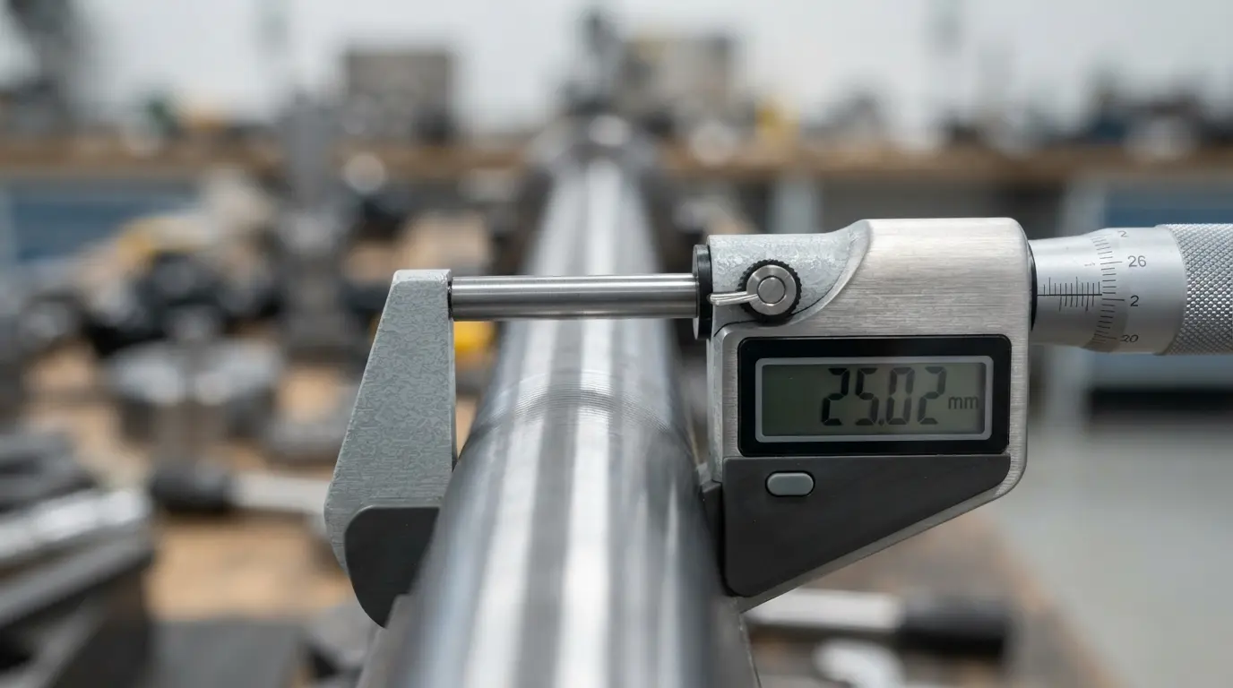
"Plus or minus 0.02mm." Engineers write this on drawings every day. But what does it actually mean in the real world? How small is 0.02mm? How does it compare to things you can actually see and feel?
This guide gives you a visual, practical understanding of CNC machining tolerances. No formulas. No standards references. Just a clear explanation of what different tolerance values mean, what they cost, and when you actually need them.
What Is Tolerance?
Tolerance is the allowed variation from a specified dimension. No manufacturing process produces a dimension that is exactly perfect every time. Tolerance defines how much variation is acceptable.
If a drawing specifies a shaft diameter of 25.00mm plus or minus 0.05mm, it means:
- The smallest acceptable diameter is 24.95mm
- The largest acceptable diameter is 25.05mm
- The total allowed variation is 0.10mm (the tolerance band)
Any shaft measured between 24.95mm and 25.05mm passes inspection. Anything outside this range is rejected.
Tolerance Values Compared to Everyday Objects
Here is where tolerance becomes real:
| Tolerance | Total Band | How Small Is That? |
|---|---|---|
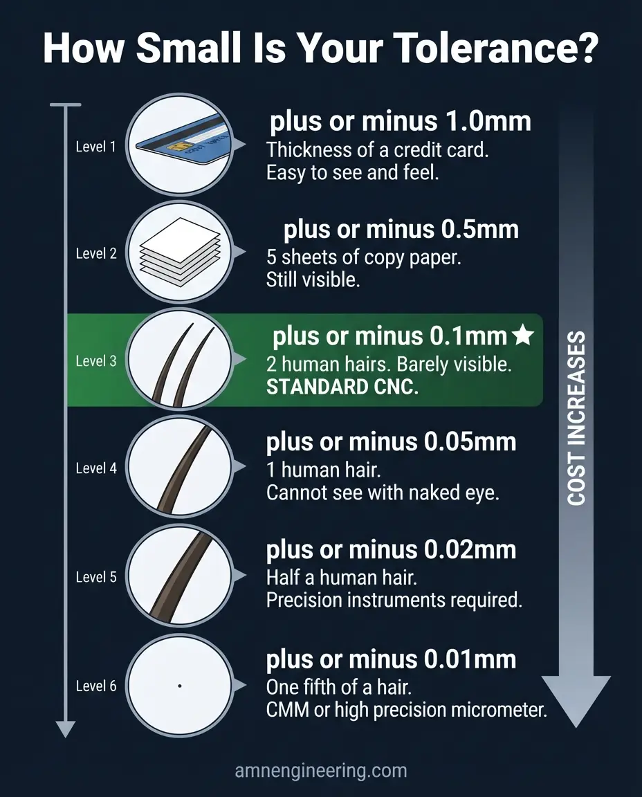
| Plus or minus 1.0mm | 2.0mm | About the thickness of a credit card. You can easily see and feel this. |
| Plus or minus 0.5mm | 1.0mm | About the thickness of 5 sheets of copy paper stacked. Still visible. |
| Plus or minus 0.1mm | 0.2mm | About the thickness of 2 human hairs side by side. Barely visible. |
| Plus or minus 0.05mm | 0.1mm | About the thickness of 1 human hair. Cannot see with naked eye. |
| Plus or minus 0.02mm | 0.04mm | Half the thickness of a human hair. Requires precision instruments to measure. |
| Plus or minus 0.01mm | 0.02mm | One fifth the thickness of a human hair. Requires a CMM or high precision micrometer. |
Key perspective: A tolerance of plus or minus 0.02mm means the part can vary by less than half the width of a human hair. That is extremely precise. It requires slow machining, careful measurement, and specialized tooling.
Common Tolerance Levels in CNC Machining
| Tolerance Level | Range | When Used | Process |
|---|---|---|---|
| Rough | Plus or minus 0.5 to 1.0mm | Non critical dimensions, structural parts | Standard machining, fabrication |
| General | Plus or minus 0.1mm | Standard engineering parts, general fits | CNC turning, CNC milling |
| Precision | Plus or minus 0.05mm | Bearing seats, sliding fits, mating surfaces | CNC with careful setup |
| High precision | Plus or minus 0.02mm | Instrument components, tight interference fits | CNC with fine finishing passes |
| Ultra precision | Plus or minus 0.01mm | Gauge surfaces, aerospace critical features | CNC + grinding |
| Sub micron | Plus or minus 0.005mm or less | Optical, semiconductor | Specialized grinding/lapping |
For most general engineering parts, plus or minus 0.1mm is more than adequate. Only specify tighter tolerances on dimensions that actually require them.
How Tolerance Affects Cost
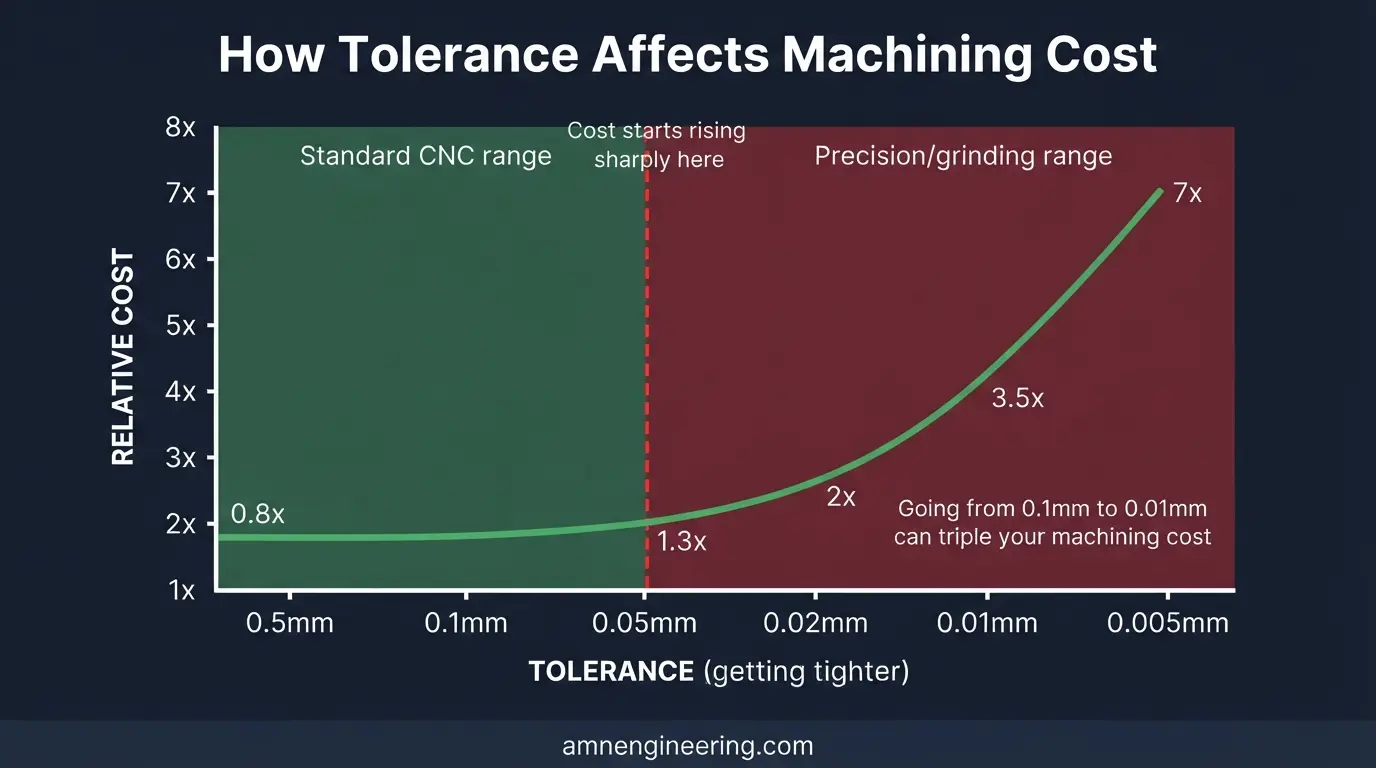
Tighter tolerances cost more. The relationship is not linear. It is exponential. Going from plus or minus 0.1mm to plus or minus 0.05mm might add 20 to 30 percent to the machining cost. Going from plus or minus 0.05mm to plus or minus 0.01mm might double or triple it.
| Tolerance | Relative Machining Cost | Why |
|---|---|---|
| Plus or minus 0.5mm | 0.8x | Fast rough machining, minimal measurement |
| Plus or minus 0.1mm | 1.0x (baseline) | Standard CNC, normal measurement |
| Plus or minus 0.05mm | 1.2 to 1.5x | Slower finishing pass, careful measurement |
| Plus or minus 0.02mm | 1.5 to 2.5x | Multiple finishing passes, precision measurement |
| Plus or minus 0.01mm | 2.5 to 4x | Grinding after CNC, CMM measurement |
| Plus or minus 0.005mm | 4 to 8x | Specialized grinding/lapping, temperature controlled |
Why Tight Tolerances Cost More
Slower cutting. Finishing passes at tight tolerances use smaller cuts and slower speeds to minimize tool deflection and vibration.
More measurement time. Each part must be carefully measured with precision instruments. At plus or minus 0.01mm, every part may need individual measurement.
Tool wear matters more. As a cutting tool wears, dimensions drift. At tight tolerances, tools must be replaced or adjusted more frequently.
Temperature matters. Metal expands and contracts with temperature. At plus or minus 0.01mm, parts and measuring equipment must be at a controlled temperature. A part measured warm may be out of spec when cool.
Rejection rate increases. At very tight tolerances, some parts inevitably fall outside the acceptable range and must be scrapped or reworked.
When to Specify Tight Tolerances (and When Not To)
Specify Tight Tolerances On:
- Bearing seats: The diameter where a bearing sits must be controlled to ensure proper fit (plus or minus 0.01 to 0.02mm)
- Seal surfaces: O ring grooves and seal faces need controlled dimensions to prevent leaks
- Mating/interfacing surfaces: Where two parts must fit together precisely
- Shaft diameters for running fits: The clearance between a shaft and its housing is critical
Do NOT Overspecify On:
- Overall length of a shaft (unless it fits between two fixed points)
- Bolt hole locations (plus or minus 0.5mm is usually fine)
- Non functional surfaces (the outside of a bracket that bolts to a frame)
- Chamfers and radii (plus or minus 0.5mm is standard)
- Surface finish on hidden faces
The Golden Rule
Specify the tolerance the function requires, not the tightest tolerance you can imagine. A pump shaft with plus or minus 0.02mm on the bearing seats and plus or minus 0.5mm on the overall length is well specified. The same shaft with plus or minus 0.02mm on every dimension is overspecified and unnecessarily expensive.
How to Read Tolerances on a Drawing
General Tolerance Block
Most drawings have a general tolerance note (usually in the title block) that applies to all dimensions not individually toleranced:
"Unless otherwise stated: Linear dimensions plus or minus 0.1mm, Angular dimensions plus or minus 0.5 degrees"
This means every dimension on the drawing without its own tolerance note must be held to plus or minus 0.1mm.
Individual Tolerances
Critical dimensions are toleranced individually on the drawing:
"Diameter 25.00 plus 0.02 minus 0.00" means the diameter must be between 25.00mm and 25.02mm. This is a unilateral tolerance (variation allowed in one direction only).
"Diameter 25.00 plus or minus 0.02" means the diameter must be between 24.98mm and 25.02mm. This is a bilateral tolerance (equal variation allowed in both directions).
Frequently Asked Questions
It means the actual dimension can vary by up to 0.02mm above or below the target value. The total acceptable range is 0.04mm, which is less than half the thickness of a human hair.
Plus or minus 0.1mm is standard for most general engineering CNC work. This is adequate for the vast majority of machined parts.
Going from plus or minus 0.1mm to plus or minus 0.02mm typically adds 50 to 150% to the machining cost of that feature. Going to plus or minus 0.01mm can double or triple total cost.
When the tolerance is plus or minus 0.01mm or tighter, or when the surface finish needs to be Ra 0.4 or smoother. Grinding after CNC machining achieves both tight tolerance and fine surface finish.
Yes, and you should. Specify tight tolerances only on functional features (bearing seats, seals, mating surfaces) and standard tolerances on everything else. This keeps cost down while maintaining quality where it matters.