Sheet Metal Bending Tolerances and How to Specify Them
By Adil, Managing Director at AMN Engineering · · 6 min read
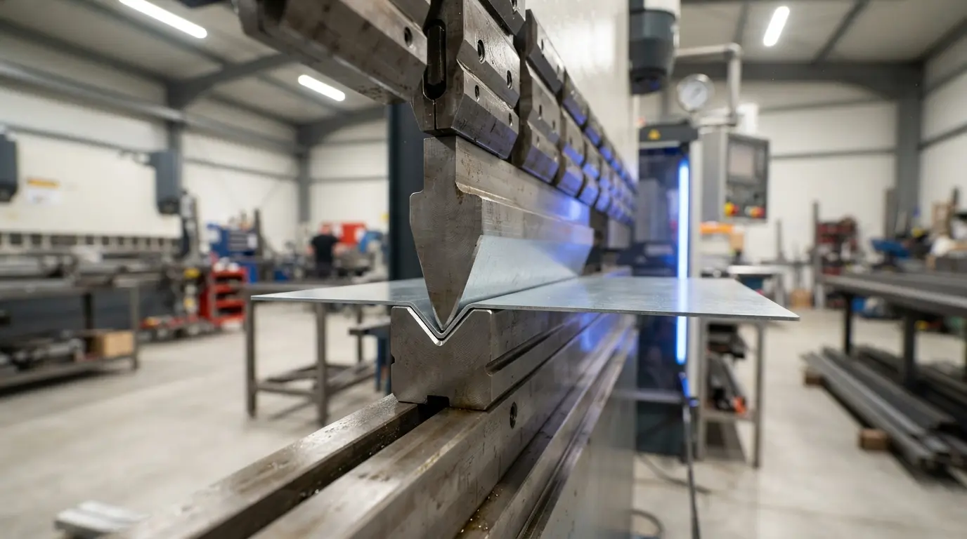
Sheet metal bending on a press brake looks simple. But achieving consistent angles, dimensions, and positions across a batch of parts requires understanding the tolerances the process can realistically hold.
This guide explains what bending accuracy you can expect, how to specify bends correctly on your drawing, and the common design mistakes that make parts harder (and more expensive) to bend.
What Tolerances Can Bending Achieve?
| Feature | Standard Tolerance | Precision (with extra care) |
|---|---|---|
| Bend angle | Plus or minus 1 degree | Plus or minus 0.5 degrees |
| Bend position (from edge to bend line) | Plus or minus 0.2mm | Plus or minus 0.1mm |
| Flange length (after bend) | Plus or minus 0.3mm | Plus or minus 0.15mm |
| Overall dimension (across multiple bends) | Plus or minus 0.5mm per bend | Plus or minus 0.25mm per bend |
Key point: Tolerances stack with multiple bends. A part with 4 bends could have plus or minus 2mm on overall dimensions (4 x 0.5mm) under standard tolerances. If your overall dimension is critical, specify it directly on the drawing so the operator can adjust individual bends to hit the total.
Bend Angle Accuracy
Standard press brake bending holds angles to plus or minus 1 degree. A 90 degree bend may come out between 89 and 91 degrees under standard practice.
Factors That Affect Angle Accuracy
Material thickness variation. Sheet metal comes from the mill with a thickness tolerance (e.g., 3mm sheet may actually be 2.9 to 3.1mm). Thicker material bends to a slightly different angle than thinner material under the same press force.
Material hardness variation. Different batches of the same grade can have slightly different yield strengths, which affects springback (see below).
Grain direction. Bending parallel to the rolling direction gives different results than bending across it. For critical angle work, specify the grain direction on your drawing.
Bend Radius Rules
Minimum Bend Radius
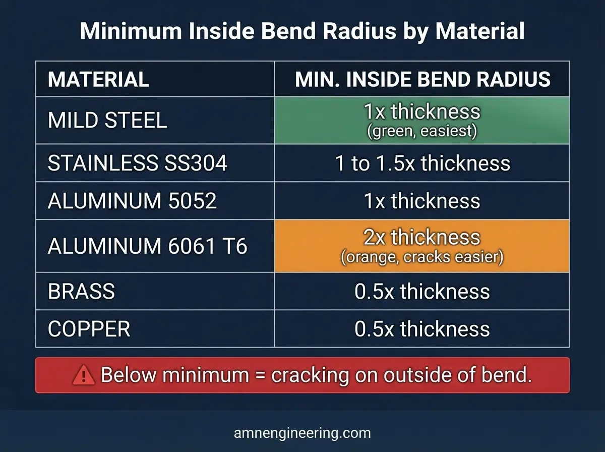
Every material has a minimum bend radius below which the outer surface of the bend will crack. As a general rule:
| Material | Minimum Inside Bend Radius |
|---|---|
| Mild steel | 1x material thickness |
| Stainless steel (SS304) | 1x to 1.5x material thickness |
| Aluminum 5052 | 1x material thickness |
| Aluminum 6061 T6 | 2x material thickness (harder, cracks easier) |
| Brass | 0.5x material thickness |
| Copper | 0.5x material thickness |
For 3mm mild steel, the minimum inside bend radius is 3mm. Specifying a 1mm radius on 3mm mild steel will result in cracking on the outside of the bend.
Standard Bend Radius
If you do not specify a radius, the fabricator will use whatever tooling they have available (typically 1 to 2mm radius for thin sheet, proportionally larger for thicker material). If a specific radius matters for your application, state it on the drawing.
Minimum Flange Length
The flange is the flat portion of material after the bend. If the flange is too short, the press brake cannot grip the material properly and the bend will be inaccurate or the part will slip.
Minimum Flange Rule
Minimum flange length = 4 times material thickness (but never less than 6mm regardless of thickness)
| Material Thickness | Minimum Flange Length |
|---|---|
| 1mm | 6mm |
| 2mm | 8mm |
| 3mm | 12mm |
| 4mm | 16mm |
| 6mm | 24mm |
Designing a flange shorter than this minimum means the part either cannot be bent on a standard press brake or requires special tooling that adds cost.
Springback: Why Parts Do Not Stay at Exact Angle
When the press brake releases the material, the part "springs back" slightly toward its original flat shape. A part bent to 90 degrees in the die might spring back to 91 or 92 degrees.
How Fabricators Handle Springback
Experienced operators compensate by overbending slightly. If the target is 90 degrees and the material springs back 2 degrees, they bend to 88 degrees. The part then springs back to 90 degrees.
Materials with More Springback
High strength steels, stainless steel, and aluminum (especially hardened tempers like 6061 T6) have more springback than mild steel. This makes them harder to bend to precise angles and is one reason stainless steel parts cost more to fabricate.
How to Specify Bending on Your Drawing
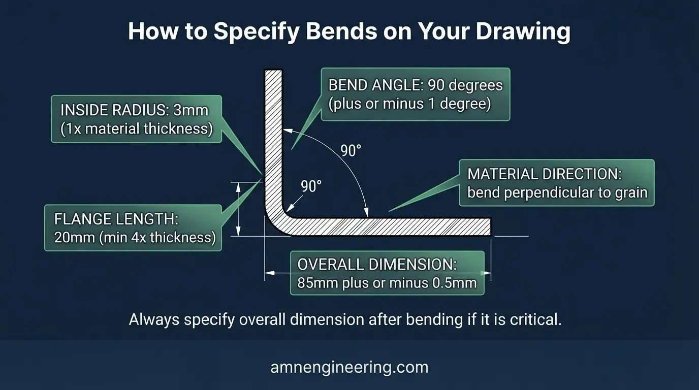
Include these details on your drawing for any bent part:
- Bend angle (e.g., 90 degrees, 120 degrees)
- Bend direction (up or down, inside or outside, clearly shown in the cross section view)
- Inside bend radius (if specific radius is required)
- Overall dimensions after bending (not just flat pattern dimensions)
- Tolerance on critical dimensions (especially overall dimensions across multiple bends)
- Material grain direction (if angle accuracy is critical)
Best practice: Provide both a flat pattern (DXF for laser cutting) and a 3D model or dimensioned bent view (STEP or PDF) so the fabricator can verify the flat pattern matches the intended bent shape.
Common Mistakes
Flange too short. The most common design error. Check minimum flange lengths before finalizing.
Bends too close together. Two bends close together interfere with each other during forming. Minimum distance between parallel bends should be 6 times material thickness or more.
Specifying bend radius smaller than minimum. Results in cracking on the outside of the bend. Always check minimum radius for your material.
Not accounting for tolerance stacking. If a part has 4 bends and each has plus or minus 0.5mm, the overall dimension has plus or minus 2mm accumulation. Specify the overall dimension directly if it is critical.
Not showing bend direction. If the drawing does not clearly show which way the flanges bend, the part may come out mirrored (bent the wrong way).
Frequently Asked Questions
Plus or minus 1 degree on angle and plus or minus 0.2 to 0.3mm on bend position for standard press brake work.
1x material thickness. For 3mm steel, the minimum inside radius is 3mm.
Springback. The material springs back slightly after the press releases. Fabricators compensate by overbending. Some materials (stainless, aluminum 6061) have more springback than others.
4 times material thickness, minimum 6mm. Shorter flanges cannot be gripped properly by the press brake.