Laser Cutting for Brackets, Panels, and Enclosures: Design Tips That Save Cost
By Adil, Managing Director at AMN Engineering · · 6 min read
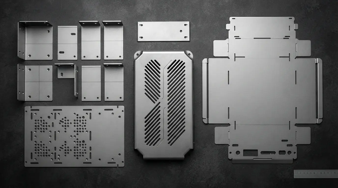
Laser cutting can produce virtually any 2D shape from sheet metal. But a well designed part cuts faster, wastes less material, bends more easily, and assembles without problems. A poorly designed one wastes sheet, cracks at bends, and requires rework.
These tips come from years of cutting brackets, panels, guards, and enclosures at AMN Engineering. Each tip saves you money or prevents a quality problem.
Why Design Matters for Laser Cut Parts
The laser cuts whatever geometry your DXF file contains. It does not warn you that your holes are too close to the edge, your bend will crack, or your nesting wastes 40 percent of the sheet. Design decisions made in CAD directly affect cost, quality, and lead time.
Tip 1: Minimum Hole Sizes
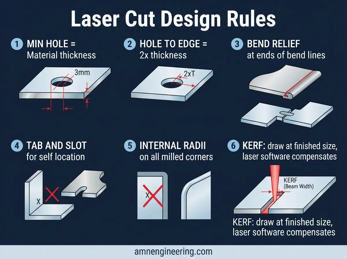
The laser can cut very small holes, but there is a practical minimum for good quality:
Minimum hole diameter = material thickness
For 3mm steel, the minimum hole is 3mm diameter. Smaller holes are possible but edge quality degrades, the hole may not be perfectly round, and cutting speed drops significantly.
For slots, minimum slot width = 1.5x material thickness. A 3mm sheet should have slots at least 4.5mm wide.
Tip 2: Hole to Edge and Hole to Hole Spacing
Hole center to edge: minimum 2x material thickness from the nearest edge. For 3mm steel, keep holes at least 6mm from any edge. Closer than this risks material deformation during bending or distortion from cutting heat.
Hole to hole: minimum 2x material thickness between hole edges (not centers). Two 10mm holes in 3mm steel should have at least 6mm of material between them.
These minimums ensure structural integrity around holes and prevent the thin web between features from distorting.
Tip 3: Bend Relief Cuts
When a bend line meets a cut edge or another feature, the material can tear or deform at the intersection. Bend relief cuts prevent this.
What to do: Add a small cut (slot or radius) at each end of the bend line where it meets an adjacent edge. The relief cut should be:
- Width: equal to or slightly larger than the material thickness
- Length: extends past the bend line by at least 1mm
This allows the material to fold cleanly along the bend line without pulling or tearing the adjacent flat section.
Tip 4: Tab and Slot Self Locating Features
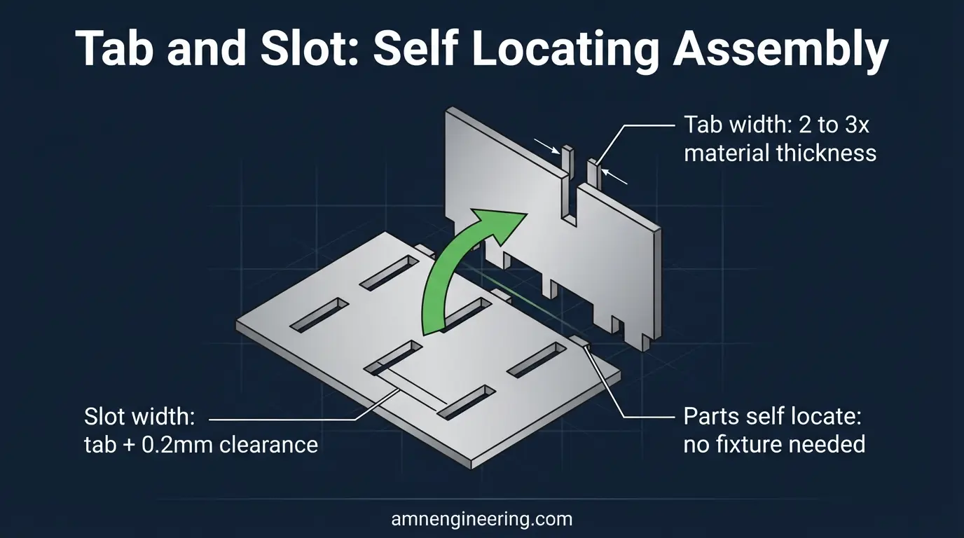
For parts that will be welded into assemblies, design tab and slot features that lock parts together before welding. This eliminates the need for complex welding fixtures and ensures consistent alignment.
Tab width: 2 to 3 times material thickness. For 3mm steel, tabs should be 6 to 9mm wide.
Slot width: Tab width plus 0.2mm (for clearance). The 0.2mm gap allows easy assembly while keeping the parts aligned.
Tab length: 10 to 20mm is typical. Enough to locate the part securely but not so long that it is hard to insert.
The laser cuts both the tab and the slot precisely, so parts self locate every time. The welder just slides them together and welds. No measuring, no clamping, no fixture.
Tip 5: Nesting Efficiency
Nesting is how parts are arranged on the sheet to minimize material waste. Good nesting uses 70 to 85 percent of the sheet. Poor nesting uses 50 to 60 percent.
Design for nesting: If you are ordering multiple different parts, design them so they interlock on the sheet. A part with a large internal cutout can have smaller parts nested inside that cutout.
Standard sheet sizes: Design your part dimensions to fit efficiently on standard sheet sizes (1220 x 2440mm, 1250 x 2500mm, 1500 x 3000mm). A part that is 630mm wide fits perfectly on a 1220mm sheet (two rows with minimal waste). A part that is 650mm wide wastes 570mm of sheet width.
Common edge cutting: If two adjacent parts share a straight edge, they can share a single cut line, saving cutting time and material.
Tip 6: Kerf Compensation
The laser beam has a width (the kerf), typically 0.1 to 0.3mm for fiber lasers. This means the cut removes a small strip of material. The laser software automatically compensates for kerf by offsetting the cutting path by half the kerf width.
What you need to know: Draw your parts at their actual finished dimensions. The laser software handles kerf compensation automatically. Do not add kerf allowance to your DXF file unless your manufacturer specifically asks you to.
Where kerf matters: For parts that fit tightly together (tab and slot assemblies, puzzle fit joints), discuss kerf compensation with your manufacturer to ensure the right clearance.
Tip 7: Corner Relief for Folded Enclosures
When designing a flat pattern for a box or enclosure that will be folded up from a single sheet, the corners where two bend lines meet need corner relief. Without relief, the material bunches up and tears at the corner.
Types of corner relief:
- Square relief: A small square cutout at the corner intersection. Simple but leaves a small gap in the finished corner.
- Radius relief: A small radius (1 to 2x material thickness) at the corner. Smoother appearance and less stress concentration.
- No relief (butt joint): The bend flanges are trimmed to meet at a butt joint and welded closed. More labor but gives a closed corner.
Common Parts and Typical Specifications
| Part Type | Typical Material | Typical Thickness | Key Design Considerations |
|---|---|---|---|
| Mounting brackets | Mild steel, SS304 | 2 to 5mm | Hole positions, bend tolerances, tab/slot for welding |
| Electrical panels | Mild steel, galvanized | 1.2 to 2mm | Knockouts, mounting holes, fold lines |
| Machine guards | Mild steel, aluminum | 1.5 to 3mm | Ventilation holes/patterns, edge safety |
| Enclosures | Mild steel, SS304 | 1.5 to 3mm | Corner relief, fold sequence, internal mounting features |
| Signage/screens | Mild steel, stainless, aluminum | 1 to 3mm | Fine detail, text as outlines, surface finish |
Frequently Asked Questions
Equal to the material thickness. For 3mm steel, minimum hole diameter is 3mm. Smaller is possible but edge quality degrades and cutting speed drops.
Minimum 2x material thickness from hole center to edge. For 3mm steel, keep holes at least 6mm from edges to avoid deformation during bending or from cutting heat.
A small cut at the end of a bend line that prevents the material from tearing at the intersection. It is essential for any part that will be bent after laser cutting.
No. Draw parts at their finished dimensions. The laser software compensates for kerf automatically by offsetting the cutting path by half the kerf width.