7 Common DXF File Mistakes That Ruin Your Laser Cut Parts
By Adil, Managing Director at AMN Engineering · · 8 min read
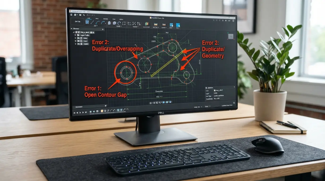
A perfect DXF file means your laser cut parts come out perfect on the first run. A bad DXF file means wasted material, wrong dimensions, double cut edges, and delays while your manufacturer emails you asking for corrections.
We receive hundreds of DXF files every month at AMN Engineering. These 7 mistakes account for 90 percent of the problems we see. Fix them before sending and your parts will be right the first time.
Why DXF Quality Matters
The laser cutter reads your DXF file and follows the lines exactly. It does not interpret, guess, or fix errors. If a line is open, the laser does not close it. If two lines sit on top of each other, the laser cuts the same path twice. If the scale is wrong, every dimension is wrong.
Your DXF file IS your part. The quality of the file directly determines the quality of the cut.
Mistake 1: Open Contours
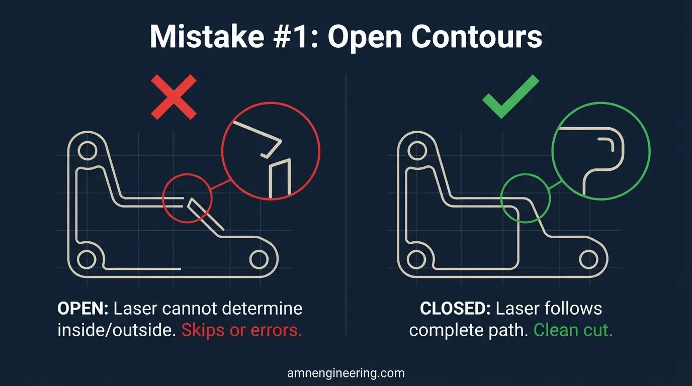
The problem: The outline of your part has a gap where two line segments do not connect. The gap might be 0.001mm and invisible on screen, but the laser sees it as an open path and cannot determine what is inside and outside.
What happens: The laser may skip the profile entirely, cut only part of it, or produce an error that stops the machine. The operator has to stop, find the gap, and fix it manually, which delays your order.
How to fix: In your CAD software, use the "join" or "close polyline" command. Most programs have a tolerance setting for joining endpoints that are close but not touching. Set it to 0.01mm and join all profiles. Then verify each profile is a closed polyline with zero gaps.
Prevention: Draw profiles as polylines from the start rather than individual line segments. A continuous polyline cannot have gaps between segments.
Mistake 2: Duplicate Lines
The problem: Two identical lines sit exactly on top of each other. This usually happens when you copy geometry, mirror a profile, or import from another file without cleaning up overlaps.
What happens: The laser cuts the same path twice. This creates a wider kerf (cut slot), rougher edge quality, and potential burn marks on the material. On thin material, double cutting can burn through and damage adjacent features.
How to fix: Use the "delete duplicates" or "overkill" command in your CAD software. In AutoCAD, the command is OVERKILL. In most other programs, look for "remove overlapping geometry" or "purge duplicates."
Prevention: After any copy, mirror, or import operation, always run a duplicate check before saving.
Mistake 3: Wrong Scale or Units
The problem: Your file was drawn in inches but the manufacturer reads it as millimeters, or vice versa. A 100mm part drawn in inches becomes 100 inches (2,540mm) or a 4 inch part drawn in millimeters becomes 4mm.
What happens: Parts come out 25.4 times too large or too small. The material is wasted. The order is delayed while the error is identified and corrected.
How to fix: Always check your CAD software unit settings before exporting. Add a note on your drawing: "All dimensions in mm" or "All dimensions in inches." Include at least one overall dimension on the DXF file or accompanying PDF so the manufacturer can verify scale immediately.
Prevention: Set your CAD template to millimeters and never change it. Millimeters are the global standard for manufacturing. If you receive files in inches, convert before sending to the manufacturer.
Mistake 4: Text Not Converted to Outlines
The problem: Your DXF includes text labels, part numbers, or logos as editable text objects. The laser machine may not have the same font installed, causing the text to display incorrectly or not at all.
What happens: Text appears in the wrong font, wrong size, or as empty boxes. If the text is meant to be laser engraved or cut into the part, the result will be wrong or missing.
How to fix: Convert all text to outlines (also called "curves" or "explode text") before exporting the DXF. This turns the text into vector geometry that the laser reads as shapes, not font characters.
Prevention: Always convert text to outlines as the last step before saving the DXF for manufacturing. Keep a separate editable version for your records.
Mistake 5: Construction Lines Left in the File
The problem: Your DXF still contains construction lines, center lines, dimension lines, notes, or reference geometry that was used during design but is not part of the actual cut profile.
What happens: The laser may attempt to cut along construction lines, creating unwanted cuts on your material. Or the operator has to manually identify and delete the extra geometry before cutting, which delays your order and risks mistakes.
How to fix: Put your cutting profile on one dedicated layer (e.g., "CUT" or "0"). Delete or hide all other layers before exporting. The DXF file should contain ONLY the geometry you want the laser to cut.
Prevention: Use a consistent layer structure from the start: one layer for cut profiles, separate layers for dimensions, notes, and construction geometry. Export only the cut layer.
Mistake 6: Tiny Gaps Between Line Segments
The problem: Your profile looks closed on screen but is actually made of many short line segments with microscopic gaps between them. This commonly happens when importing from PDF, converting from raster images, or using automatic trace tools.
What happens: The laser treats each segment as a separate cut, lifting between segments. This creates small uncut spots on the profile, rough edges, and slower cutting speed (the laser decelerates and accelerates at every gap).
How to fix: Select all segments and join them into a single polyline. If the gaps are too large to auto join, manually close each gap. For files converted from images, redraw the profile properly in CAD rather than using the traced version.
Prevention: Never send traced or auto converted DXF files without cleaning them up. Tracing tools produce hundreds of tiny segments that look smooth on screen but perform badly on the laser.
Mistake 7: Wrong Layer Structure
The problem: Your DXF has geometry on multiple layers but no indication of which layer is the cut profile, which is engraving, and which is reference geometry. Or all geometry is on layer "0" mixed together.
What happens: The operator has to guess which lines to cut and which to ignore. This leads to: cutting reference lines, skipping actual profiles, or delaying the job while they contact you for clarification.
How to fix: Use a clear layer naming convention:
- "CUT" for through cut profiles
- "ENGRAVE" or "MARK" for surface engraving
- "BEND" for bend lines (if combining with fabrication)
- "REF" or "INFO" for reference geometry (delete before sending, or clearly name the layer)
Prevention: Establish a layer standard and use it consistently. Many laser cutting shops have their own preferred layer names. Ask your manufacturer what they prefer.
DXF Checklist Before Sending
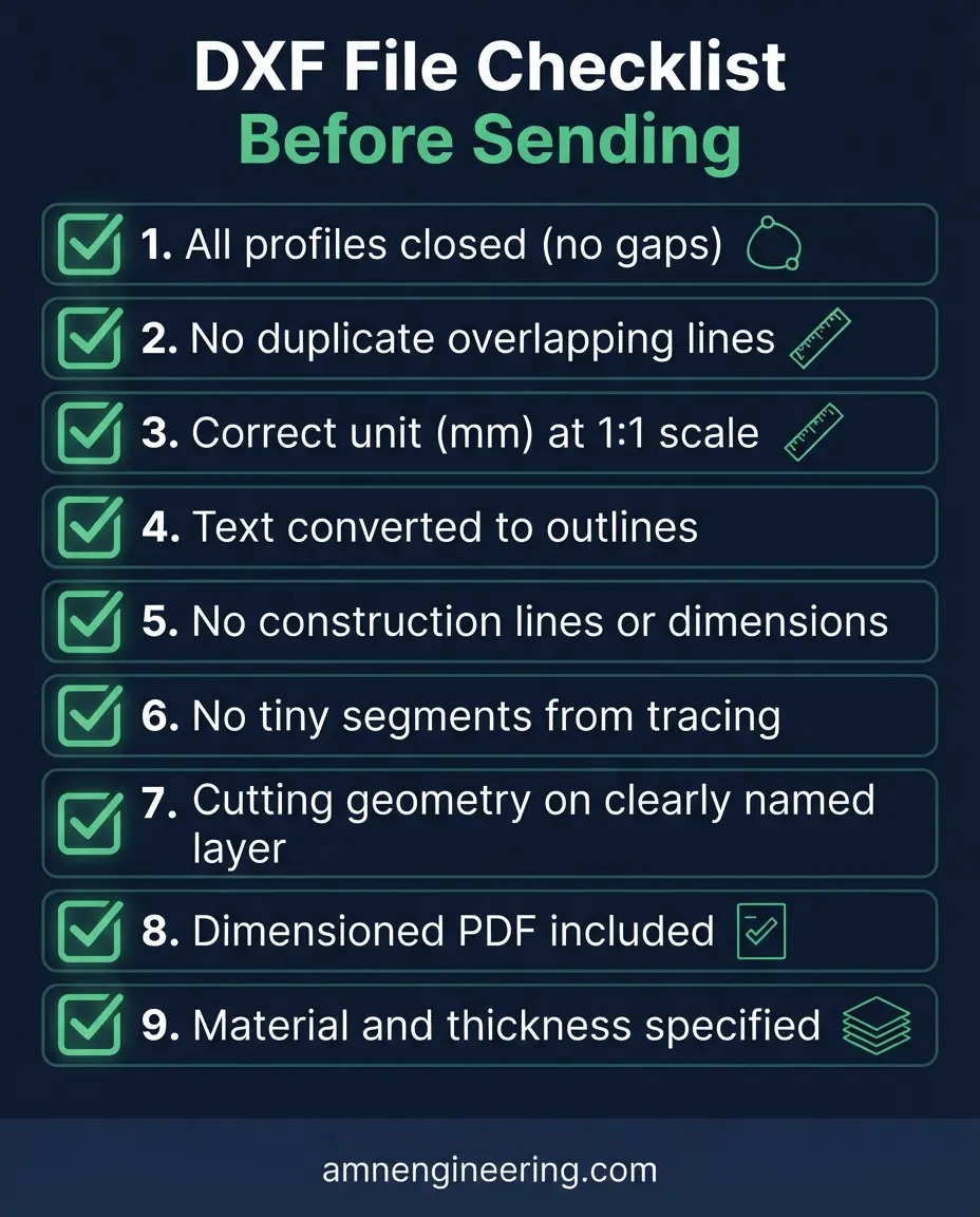
Use this checklist every time you send a DXF file for laser cutting:
- All profiles are closed polylines (no gaps)
- No duplicate overlapping lines
- File is in the correct unit (mm) and at 1:1 scale
- All text is converted to outlines
- No construction lines, dimensions, or notes in the cut file
- Profiles are clean (no tiny segments from tracing)
- Cutting geometry is on a clearly named layer
- A dimensioned PDF is included for reference
- Material and thickness are specified
Frequently Asked Questions
Open contours (gaps in the profile). This is the single most frequent problem and causes the laser to skip or error on that profile.
In AutoCAD use the OVERKILL command. In other CAD programs look for "remove duplicates" or "purge overlapping geometry." Select all and run the cleanup.
Millimeters. This is the global manufacturing standard. If your CAD software uses inches, convert before exporting. Always state the unit on the accompanying drawing.
A PDF is useful as a reference for dimensions and notes, but the laser machine reads DXF geometry directly. Converting PDF to DXF often introduces tiny segments and gaps. Send a proper DXF plus a PDF for reference.