Designing Parts for Die Casting: Draft Angles, Wall Thickness, and Tolerances
By Adil, Managing Director at AMN Engineering · · 6 min read
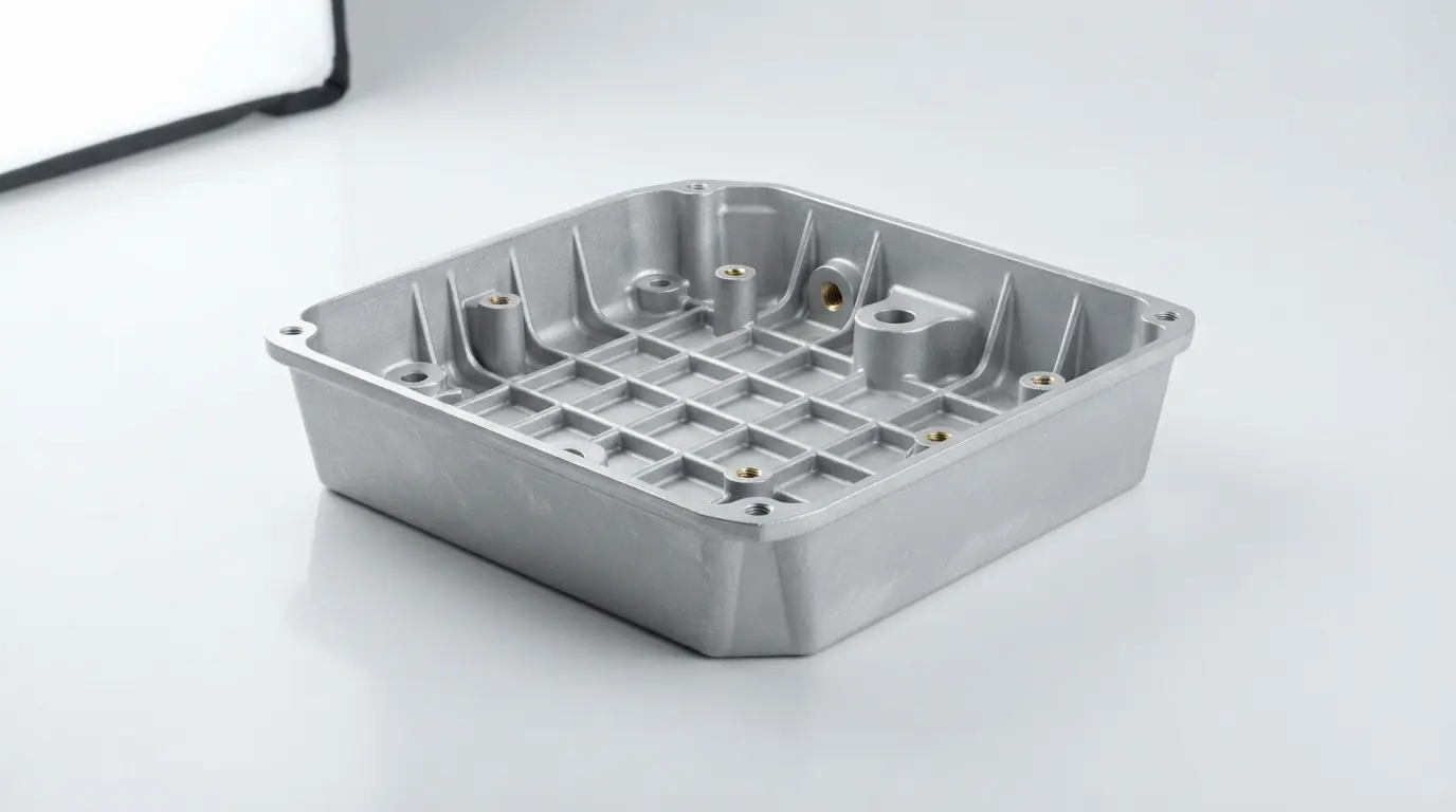
A well designed die cast part ejects cleanly from the mold, fills completely, cools uniformly, and meets dimensional tolerances on the first run. A poorly designed one sticks in the die, has porosity, warps during cooling, and needs expensive mold modifications to fix.
The difference is almost always in the design, not the manufacturing. This guide covers the essential design rules for die casting: draft angles, wall thickness, tolerances, parting lines, and feature design. Following these rules before your part reaches the die caster saves thousands of dollars in mold modifications and quality problems.
Why Design for Die Casting Matters
Die casting molds cost $5,000 to $50,000 or more. Modifying a mold after it is built costs 20 to 50 percent of the original mold price. Getting the design right before the mold is cut is far cheaper than fixing problems afterward.
The rules below apply to aluminum, zinc, and magnesium die casting. Each material has slightly different optimal values, but the principles are the same.
Draft Angles: The Most Important Rule
Draft angle is the slight taper applied to vertical surfaces so the part can eject from the mold without sticking or scratching.
Minimum Draft Angles
| Surface Type | Minimum Draft |
|---|---|
| External walls | 1 to 2 degrees |
| Internal walls (cores) | 2 to 3 degrees |
| Deep ribs (depth greater than 3x width) | 3 to 5 degrees |
| Textured surfaces | Add 1 degree per 0.025mm texture depth |
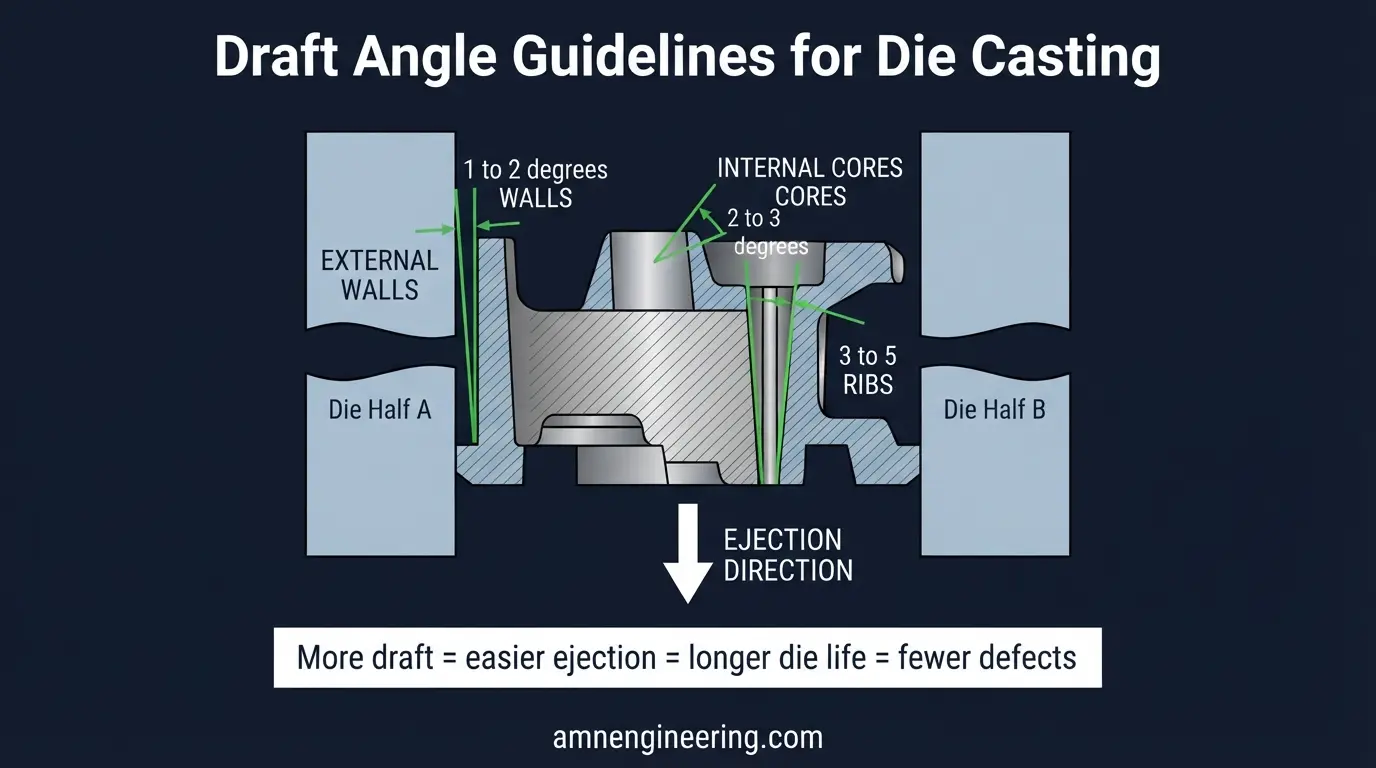
What Happens Without Enough Draft
- Part sticks in the die and requires force to eject
- Ejector pins leave marks or deform the part
- Die surfaces wear faster, reducing mold life
- Surface finish degrades on the stuck areas
Rule: when in doubt, add more draft. Extra draft costs nothing. Too little draft costs you mold repairs and scrap parts.
Wall Thickness Guidelines
Uniform wall thickness is critical in die casting. Thick sections cool slower than thin sections, causing shrinkage porosity, sink marks, and internal voids.
Recommended Wall Thickness by Material
| Material | Minimum Wall | Recommended Wall | Maximum Wall |
|---|---|---|---|
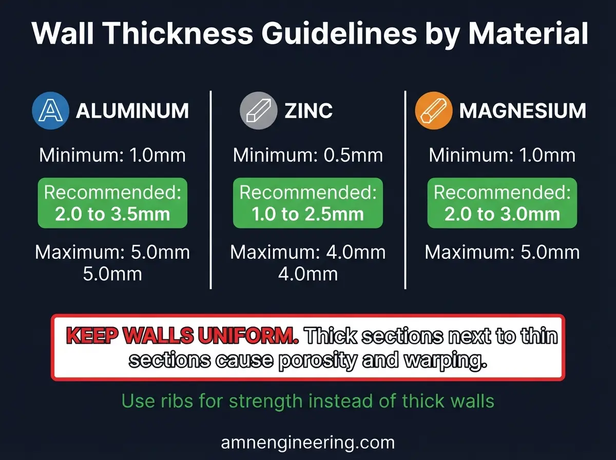
| Aluminum | 1.0mm | 2.0 to 3.5mm | 5.0mm |
| Zinc | 0.5mm | 1.0 to 2.5mm | 4.0mm |
| Magnesium | 1.0mm | 2.0 to 3.0mm | 5.0mm |
Key Rules
Keep walls uniform. If your part has both 2mm and 6mm sections, the thick section will have porosity. Transition between thicknesses gradually, not abruptly.
Use ribs instead of thick walls. If you need strength, add ribs rather than making walls thicker. A 2mm wall with 1.5mm ribs is stronger and lighter than a solid 4mm wall.
Avoid hot spots. Where multiple walls, ribs, or bosses intersect, metal accumulates and creates thick sections that cool slowly. These "hot spots" are where porosity forms. Core out thick intersections to maintain uniform wall thickness.
Tolerances You Can Expect
| Feature | Achievable Tolerance |
|---|---|
| Linear dimensions (per 25mm) | Plus or minus 0.1mm |
| Across parting line | Plus or minus 0.15 to 0.25mm |
| Hole diameter (cored) | Plus or minus 0.1mm |
| Flatness (per 25mm) | 0.05mm |
| Angularity | Plus or minus 0.5 degrees |
For tighter tolerances on critical features (bearing bores, mating surfaces, hole positions), plan for CNC machining after casting. Die casting produces the near net shape. Machining brings critical features to final tolerance.
Parting Lines and How to Position Them
The parting line is where the two halves of the die meet. It leaves a visible line on the cast part. Position it where:
- It is least visible on the finished part
- It does not cross critical or sealing surfaces
- It allows the simplest die design (reducing mold cost)
- Flash (thin metal that squeezes between die halves) can be easily removed
Discuss parting line placement with your die caster before finalizing the design. Moving a parting line after the mold is built requires a new mold.
Ribs, Bosses, and Fillets
Ribs
- Rib thickness: 50 to 75% of the adjacent wall thickness
- Rib height: maximum 3 to 5 times the rib thickness
- Draft on ribs: 2 to 5 degrees minimum
- Space ribs at least 2 times wall thickness apart
Bosses (for screws or inserts)
- Boss wall thickness: equal to the main wall thickness
- Boss height: maximum 2.5 times the outer diameter
- Core bosses (hollow center) to prevent thick sections
- Add fillet radius at the base (minimum 0.5mm)
Fillets and Radii
- Add fillets to ALL internal corners (minimum 0.5mm radius, 1mm or more preferred)
- Sharp internal corners cause stress concentrations and die wear
- External corners can have smaller radii (0.25mm minimum)
Common Design Mistakes
No draft angles. The most common mistake. Every surface that is perpendicular to the parting line needs draft.
Non uniform walls. Thick sections next to thin sections cause porosity and warping. Keep walls as uniform as possible.
Sharp internal corners. Always fillet. Sharp corners cause die wear and part cracking.
Undercuts without slides. Undercuts (features that prevent straight ejection) require side slides in the die, adding complexity and cost. Eliminate undercuts from the design wherever possible.
Specifying tolerances tighter than the process can hold. Die casting holds plus or minus 0.1mm on linear dimensions. If you need plus or minus 0.02mm, plan for post casting machining.
Frequently Asked Questions
1 to 2 degrees minimum on external surfaces, 2 to 3 degrees on internal surfaces and cores. Deep features need 3 to 5 degrees. More draft is always better.
1.0mm absolute minimum, 2.0 to 3.5mm recommended. Keep walls uniform to prevent porosity.
Yes. Most die cast parts need machining on critical features like bearing bores, mating surfaces, and threaded holes. Die casting produces the shape. CNC machining produces the precision.
Keep walls uniform, avoid thick intersections, use ribs instead of solid walls, add adequate venting in the die design, and discuss process parameters with your die caster.
$5,000 to $50,000+ depending on part size, complexity, number of cavities, and die material. Mold cost is amortized across production volume.